
Contents of this page:
- Setting up the microscope
- Setting up the lamp
- Focal length and magnification
- Slide making with Meltmount
- Slide making with Glycerine gel
- Cover slips
- Interference colours and birefringence
- The red plate
- Uniaxial crystals and twinkling
- Refractive index relative to the mounting medium
- Pre-decimalization currency
- Test yourself
Setting up the microscope for Köhler illumination, also adjusting and using it.
To get the best image with a microscope one needs to set all the adjustments correctly. This is the object of setting up. Some of the adjustments depend on the objective that is used, and so need to be altered every time an objective is changed; others depend on the thickness of the slide and if a very thick slide follows a normal one, an adjustment may need to be made if the work is critical. Some adjustments should remain in position, once they are set, for long periods, but cleaners, and other users of the microscope may inadvertently re-set them to incorrect positions.
Diagram of the light paths through the microscope contributed by Kostas Ntanos
1. Try to use a X10 objective to start setting a microscope up, but if one is not available choose one with a greater magnification. However do not start by using an objective that has a greater magnification than X20. Switch on the light. If the microscope is fitted with binocular eyepieces, you will find that at least one of the eyepieces can be focused by turning a knurled ring on the eyepiece mount. There should be a cross wire or scale in one of the eyepieces: make sure that the plain eyepiece is in the focusing mount. The eyepiece with the cross wire in it should have a focusing adjustment on the eyepiece itself. Look through this eyepiece when it is out of the microscope, try to relax your eye so that it is focused as for distant vision, and twist the adjustment till the cross wires become sharp. Put this eyepiece into the non-focusing eyepiece mount.
2. Place a slide on the stage. Adjust the position of the objective so that it is almost touching the slide. (With some objectives you may not be able to bring the objective closer to the slide than a certain distance, if this is the case accept that position.) Look down the microscope and increase the distance between the slide and the objective till the slide comes into focus for the eye which will also see the cross wires. Adjust the light with the voltage control so that the image is bright enough.
If you are using a binocular microscope, adjust the separation of the eyepieces so that you can see the slide comfortably with each eye. On most polarising microscopes, this will mean sliding the eyepieces apart or moving them closer together, and this will also have the effect of changing the physical tube length. To compensate for this change, note the reading on the scale, which will probably run from about 55 to 75, and then rotate each eyepiece mount so that the same reading occurs against the index. (Sliding heads where the tube length is compensated automatically have been manufactured.) Where the binocular head is in the form of a hinge rather than a slider no change in tube length will occur when an adjustment in eyepiece separation is made. Unfortunately, this type of head, which is used on most biological microscopes, is unsuitable for use on a polarising microscope, as the cross wires would not remain lined up with the directions of the polariser and analyser. If the image which does not include the cross wires or scale is not sharp, adjust the ring on the focusing mount so that both eyes are seeing a sharp image. If the scale or cross wires themselves are not sharp, you can bring them into focus by rotating part of the eyepiece itself not the mount on the binocular head. Different people will require different settings for the separation of the eyepieces, for the focusing mount on the plain eyepiece, and for the focus setting on the cross wired eyepiece.
If you are using a monocular microscope and the cross wires themselves are not sharp, although the image of the specimen is, you can bring the wires into focus, by rotating part of the eyepiece itself. You can work with whichever eye you prefer, but you may need to change this setting on the eyepiece if you change from one eye to the other. You will probably be better off using your dominant eye. To find out which eye this is, look at some object on the far side of the room, and keeping both eyes open, very rapidly point at it. Do not move your head or finger, but close one eye after the other and find out which eye most nearly lines up with your finger and the object. This is your dominant eye. You may need to repeat this test a few times before you are sure which eye is dominant. When using a monocular microscope, although you only use one eye to look down the microscope, try to keep the other eye open. It takes a little practice to do this, but once you have learned to concentrate on the image from one eye, you will find that if you keep both eyes open you have far less trouble with eye strain when you need use the microscope for long periods. You can learn to use the non-dominant eye, but it is more difficult to concentrate on the image rather than on the clutter on the bench. You may find you need to lightly close the other eye for a few moments while you are finding what you are trying to look at and your brain is ‘locking onto the image’. Once you have ‘locked on’, the other eye tends to open up.
3. Rotate the stage and check the centring of the objective, and adjust if necessary. Use the centring screws on the nosepiece or the objective changer to do this. Some Zeiss pol. objectives have a built-in centring system consisting of two knurled rings. Some people find centring very difficult. There are always two adjusters. Usually one adjuster moves the objective on a line from NE to SW and the other from NW to SE. Until you become skilled, you should only move one adjuster at a time, even if it does mean that you have to move the objective like a boat tacking into the wind. There are two main methods.
First method: Bring a particle so that it is directly under the cross wires, then rotate the stage through 180 degrees. If the objective is centred, the particle will still be under the cross wires. If it is not the particle will assume a new position away from the centre. Use the centring adjustments to move the particle till it is half-way between the new position and the centre. Move another particle under the cross wires, and check whether it moves away from that position. If it does repeat the adjustment.
Second method: Rotate the stage and watch for a place in the field of view where the particles are moving slowly in a small circle. With the adjusting screws move the centre of that circle to the cross wires. Even if the centre is outside the field of view you should be able to estimate roughly where it is and make adjustments so that you can see it. Then you can move it to the cross wires.
N.B. With some ball bearing stages you will find that the centre of the stage is moved very slightly each time the stage is rotated.
4. Close the field diaphragm.
5. Bring the image of the field diaphragm into the plane of the slide by raising or lowering the substage condenser. Try to make the edge of the ring of light as sharp as possible. This will vary according to the quality of the substage condenser. You may have a clean sharp edge with no colour fringes and be able to see the angles that the metal sheets make with each other, or you may have a broad band of blue or red. On some microscopes you may see three or more interlaced rings of light; if this is the case, concentrate on the brightest one which is likely to be near the middle, ignore the others.
6. If the image of the field diaphragm is not in the centre of the field of view, move it there by twisting the mirror from side to side or up and down. If the mirror is fixed, move the substage condenser with the centring screws. On a few microscopes, the substage condenser can be moved only in one direction and the mirror can only be moved at right angles to it. In this case you may need to adjust both mirror and substage condenser. If there are three rings, centre the middle, or brightest, one. Do not change the focus of the substage condenser.
7. Open the field diaphragm so that its image just fills the field of view. If you are changing from a lower to a higher powered objective you may need to close it first.
8. Introduce the Bertrand lens, If there is no Bertrand lens on the microscope, remove one of the eyepieces and look down the tube from 10-20 centimetres away. You should see a bright circle of light.
9. The aperture diaphragm controls the size of the bright circular area. Adjust it so that it is about 2/3 or 3/4 of its maximum size. For most work this is about right, but there are occasions when you will need to work with a smaller image of the aperture diaphragm, but it should never need to be smaller than 1/2 of the maximum size. You may see parallel bands running across the bright circular area. This is an image of the lamp filament. The aperture diaphragm controls the contrast in the image. If the aperture diaphragm is closed too much, the contrast will be too high, the edges of objects you see on the slide will be broad, fine detail will be lost, and spurious effects may be created due to diffraction. If the aperture diaphragm is open too far, the contrast will be weak, the edges of fine structures will be difficult to see and again detail will be lost. The aperture diaphragm also controls the amount of light that reaches the slide, however it should never be used to change this. The amount of light should be controlled by introducing neutral density filters, or by changing the voltage; never by changing the size of the aperture diaphragm.
10. Remove the Bertrand lens from the light path or replace the eyepiece.
11. View the image and reduce the voltage if the light is too bright.
12. Check the focus of the slide and adjust if necessary.
You should now have a good image. A poor image at this stage, is likely to be caused by dirt or grease on the cover slip, eyepiece, or objective. If the objective has a high NA, it could also be due to working with a cover slip of the wrong thickness.
N.B. Stages 7 to 12 will have to be repeated ever time you change one objective for another.
Setting up a microscope lamp
If the illumination system includes ground, or opaline glass, it is not necessary to set up the lamp.
If the lamp is built in and is not directly under the substage condenser, you merely need to centre the bulb. You will probably only need to do this when you replace the bulb.
If the lamp is separate, you need to center the bulb first and then adjust the position and height of the lamp. You will need to do this if you replace the bulb, and if either the lamp or microscope is moved.

To centre the bulb for Köhler illumination on a microscope with a built-in illumination system.
There should be two screws that work against a spring and allow the bulb to be moved slightly. An adjustment of even a millimetre can be relevant. Put a slide on the stage and focus it using an objective with a magnification of about x10. centre the objective if this is possible, Close the field diaphragm and focus it onto the plane of the specimen by adjusting the level of the substage condenser. Hold a piece of card under the substage condenser and then lean forward so that you can see the lower side of the card in the mirror, and using the controls on the lamp, focus the microscope lamp until the image of the filament on the card is sharp. If the mirror is contained in the base of the microscope, you can use a small separate mirror so that you can see the underneath of the card while you are focusing the image of the filament. When you look down the microscope again, you will see a circle of light which may be bordered by a coloured ring of light. (On some microscopes you will see a row of overlapping rings, in this case one near the centre will be brighter than the others. Work on this ring and ignore the others.) This ring of light should ideally be the same colour and width all round. If it is not, turn the adjustment screws till the ring width and colour are as even as you can make them. With a high quality aplanic condenser you will find that there should be no coloured edges to the field diaphragm leaves when the lamp is correctly set. You can also check the position of the filament with the Bertrand lens. Introduce the Bertrand lens and see if the whole of the back focal plane of the objective is covered by the filament, or at least if the filament is centred in the back focal plane. After checking with the x10 objective, change to an objective with a higher NA and check again. If only part of the filament is visible adjust the lamp again until the whole of the back focal plane is covered by the filament.
To set up the lamp for Köhler illumination, if you have a separate lamp.
With a separate lamp, you need to centre the bulb relative to the lamp condenser lens first, and then adjust the position of the lamp.
To centre the bulb
If the bulb is mounted in a cylindrical sleeve which can be rotated you may be able to centre the bulb by focusing the lamp on a wall and rotating the sleeve. You will see the filament rotate. If it describes a circle it is out of adjustment and the adjusting screws should be turned till the filament rotates on the spot. An alternative scheme is to put the lamp facing towards you and hold a piece of thin card 100 to 200 millimetres in front of it. Turn the lamp on and focus the filament on the card. Adjust the field diaphragm so that you can see a circle of light surrounding the filament. Adjust the screws till the filament is centred in the ring of light and the ring of light is directly in front of the lamp.
To adjust the position of the lamp
Place the lamp so that the distance from the front of the lamp to the substage condenser, including the distance from the mirror to the substage condenser is about 250mm, and the lamp is directly in front of the microscope and turn it on. Open the field diaphragm as far as it will go. Adjust the mirror so that you get some light to work by. Put a slide on the stage and focus it using an objective with a magnification of about x10. centre the objective if this is possible, Close the field diaphragm and focus it onto the plane of the specimen by adjusting the level of the substage condenser. If you cannot see an image of the field diaphragm, you will have to open the field diaphragm until you can find an edge, and then turn the mirror till you can centre the field diaphragm. Hold a piece of card under the substage condenser and then lean forward so that you can see the underneath of the card in the mirror. Adjust the focus control on the microscope lamp until the image of the filament on the card is sharp. Look down the microscope and close the field diaphragm. Bring the image of the field diaphragm to the centre of the field of view and you should see a bright circle that may be bordered by a coloured ring of light. (On some microscopes you will see a row of overlapping rings, in this case, one near the centre will be brighter than the others. Work on this ring and ignore the others.) This ring of light should ideally be the same colour and width all round, or, with a high class aplanic substage condenser, there should be no colour at all. You now have to move the lamp and mirror to achieve this. Start by rotating the lamp on its vertical axis and watch the effect on the ring of light. If the two sides become more even but the image of the diaphragm moves away from the centre of the field of view, you can bring it back by adjusting the mirror, or the lateral controls of the substage condenser. If the colour or width of the bands at the top of the ring is different from that at the bottom, you will need to adjust the tilt of the lamp, and in this case you may need to adjust the height of the lamp on the lamp column, as well as adjusting the mirror, to bring the image of the field diaphragm back to the centre of the field of view.
Using the Bertrand lens
You can also check the position of the filament with the Bertrand lens. Introduce the Bertrand lens and see if the whole of the back focal plane of the objective is covered by the filament, or at least if the filament is centred in the back focal plane. If it is not adjust the position of the lamp till it is covered and then check the colour and width of the bands. If only part of the filament is visible adjust the lamp again until the whole of the back focal plane is covered by the filament. When the filament is correctly centred and the coloured bands are even when using the x10 lens, mount a higher power lens with a larger N.A. and use the Bertrand lens, to adjust the aperture diaphragm. Check that the back focal plane is filled. If this is not the case, try adjusting the distance that the lamp is from the microscope. If this doesn’t work, it may be that the substage condenser itself does not have an adequate NA for that lens, and one must either accept it, or obtain another substage condenser. The first few times you have to set up a separate lamp, it can take quite a long time, but it becomes quicker the more times you have to do it. You can avoid the trouble if you fix the microscope and lamp to a board. You then have all the advantages of a built in system, as well as, usually, a better and more powerful lamp.
Focal length & magnification
The data in the following tables has been taken from various manufacturers.
| Focal length magnification and N.A. for common achromatic objectives | ||||
|---|---|---|---|---|
| Magnification | Focal Length mm | Focal Length ins | N.A. | Working Distance |
| x2.5 dry | 54mm | 2 inch | 0.08 | 8.7 |
| x5 dry | 32mm | 1½ inch | 0.1 | 22mm |
| x10 dry | 16mm | 2/3 inch | 0.25 | 8mm |
| x10 dry | 16.7mm | 2/3 inch | 0.22 | 5mm |
| x16 dry | 10mm | 1/3 inch | 0.35 | 2.7mm |
| x40 dry | 4mm | 1/6 inch | 0.65 | 1mm |
| x40 dry | 4mm | 1/6 inch | 0.85 | 0.5mm |
| x50 oil | 3.25mm | 1/7 inch | 1.0 | 0.5 |
| x100 oil< | 2mm | 1/12 inch | 1.3 | 0.2 |
| Focal length magnification and N.A. for some apochromatic objectives | |||
|---|---|---|---|
| Magnification | Focal Length | N.A. | Working distance |
| x10 | 16mm | 0.32 | 0.35 |
| x15 | 12mm | 0.65 | unknown |
| x25 | 8mm | 0.65 | 0.14 |
| x40 | 4mm | 0.95 | 0.09 |
| x40 oil | 4mm | 1.0 | 0.22 |
| x60 | 3mm | 0.95 | unknown |
| x63 oil | 3mm | 1.4 | 0.9 |
| x100 oil | 2mm | 1.3 | 0.9 |
Slide making with Meltmount
Meltmount is available in two forms. As a stick, and in a bottle. A stick may be fine for some work, but it is not satisfactory for the tiny samples of pigment that we make up. Meltmount is available in a range of refractive indexes. The one we use for most slides has a refractive index of 1.662, which is the same as the old Aroclor resin, and is the mountant that is assumed in the identification key.
Meltmount is the registered trademark of R. P. Cargille Laboratories Inc.
To make up slides you need: a hot plate which can work at a temperature of about 120° C, The temperature is not very critical, but should be over 100° C. You also need a glass rod with a small ball at the end of it, a small hard-stone muller, some slides and some round cover slips which are not larger than 10 mm in diameter. Most modern objectives are designed to work with cover slips of 0.17 mm. Coverslips are not available in precise thicknesses, but those sold as No 1½ have been found suitable for slides made in the way described here.
To make the glass rod with a ball on the end. Take a piece of glass rod of about 4mm diameter and about 150mm long. Heat it in the middle till it is red hot and pull it out so that a thin section is formed. Make a nick with a file in the middle of the thin part and snap the glass at this point. Return the rod to the flame, and rotate the rod so that a small ball is formed on the thin end of the rod.
To make the muller, take a piece of glass rod and heat the end in a flame so that the end is made smooth. Make a nick in the glass about 25mm from the smooth end and snap the rod at this point. Buy an elliptical cornelian or agate ring stone about 6mm by 8mm; one of its sides should be flat. Use Araldite to glue the broken glass end to the curved side of the stone so that you have a glass handle and the muller can stand on the flat side. The hot plate can be a piece of thick aluminium supported over a spirit lamp, or a large electric spatula supported upside down in a clamp. The authors have used a domestic iron, which had been fixed upside down, on its coolest setting, but iron thermostats usually have too big a range from where they switch on to where they switch off. Start by heating the bottle of Meltmount, we always put the bottle in a small, aluminium pie case just in case it cracks and the Meltmount comes out. When the Meltmount is liquid, dip the rod with a ball on the end into the Meltmount and take it out twisting the rod so that the molten resin does not fall off. Once it has set you can repeat this to make a slightly larger ball of resin on the end of the rod. If you make a ball of about 3mm in diameter you can use it to make about 15 slides, so you may not need to heat the bottle for every session. Just how many slides you can make depends on the size of the pigment particles.
To make a slide from a bottle of pigment, use a pin or needle, fitted into a handle, to lift a tiny quantity of pigment from the bottle and transfer it to a slide that you have cleaned by rubbing it with a handkerchief. Put a very small drop of alcohol (it can be isopropyl alcohol or propanol) beside the pigment and rub the pigment and alcohol with the muller to mix them. Move the muller lightly with a circular motion then lift it off the slide using a sweeping motion; do not lift is straight up. Even when you are working with scrapings from solid paint, you do not need any pressure. You are not trying to reduce the size of the particles, you are trying to ensure that each particle is separate from the next one and surrounded by the alcohol or whatever you are using. Just how much pigment to use, how to mull the pigment into the alcohol and how to lift off the muller is an art and you will have to experiment till you find out how to do it for yourself, or find someone, who has learnt the technique from me, to show you. You are aiming to get an even layer of particles on the slide where particles do not overlap, but neither do you want large spaces surrounding each particle. With many pigments you will see very little colour at this stage. With most pigments it is helpful to work on a white background so that you can see what you are doing. However, with white pigments and extenders, a black background is more useful. If you are making up a very tiny amount of pigment, mull the alcohol, or solvent, and pigment together in the usual way, then instead of sweeping the muller off, tilt it till the stone is standing on its end and wait for the pigment and solvent to run down the face of the muller onto the slide. Lift the muller off very gently. This allows one to concentrate a sample rather than dispersing it, and is useful if you only have a very few particles.
Allow the alcohol to evaporate naturally. Put the slide on the hot plate when it appears to be dry: leave one end of the slide sticking out from the plate so that you have something to get hold of. The slide will heat up and drive off any remaining solvent. Clean a cover slip by rubbing it between finger and thumb in a handkerchief. Use tweezers to put the cover slip down on the pigment and put the glass rod with the resin on it, onto the slide just at the edge of the cover slip. The resin will melt and run under the cover slip. If you have not put enough resin onto the slide, you can add some more. Add it at the same place as you put the first drop. DO NOT ADD RESIN ON THE OPPOSITE SIDE OF THE COVER SLIP. If you do, the two resin fronts will come together and trap a large air bubble. Putting the resin just beside the cover slip is critical. If you put it on top of the cover slip, you will lift the slip off the pigment. If you put it too far from the edge of the cover slip, the resin will not run underneath. If you do put the resin drop just too far from the cover slip, move the cover slip with a pair of tweezers till it just touches the resin. You will be able to see the resin move across the underside of the cover slip. If it stops when the cover slip is not quite filled, try tapping the cover slip gently with your tweezers, and you may find that you do not need to add any more resin. When your glass rod has only a little resin on it, you may need to hold the rod beside the cover slip for some time while the resin flows down the rod. You can hold the rod steady if you apply the rod vertically, and just hold the rod against the slide by pressing lightly on the top of the rod with a finger; in fact you should always hold the rod in this way. Do not use cover slips that are larger than 10mm. If you cannot get cover slips of this size, break larger ones and use the broken pieces. Air bubbles will form if you use large cover slips.
If you want to make up slides using Meltmount with other refractive indexes, you will find that if you use a lower refractive index resin, you will need to use even smaller cover slips. 8mm cover slips work well if you can get them. Otherwise take a normal cover slip and break it into smaller pieces and use the broken pieces. If you try to use larger cover slips you will find that it may be impossible to fill the entire slip and you are likely to have a lot of trouble with gas bubbles. Meltmount which has a higher refractive index than 1.662 can be used in the normal way and should run at lower temperatures.
If you need to make up slides of pigment from paint that has been taken from an object, you need to dissolve the oil or resin that has been used so that the particles separate. A suitable solvent replaces the alcohol that is used when making up slides from bottles of dry pigment. Otherwise the technique is exactly the same.
If you want to make up slides from a watercolour cake, you can work a little of the colour from the cake onto a clean brush in just the same way that you would if you were going to paint with it but use distilled or de-ionised water instead of water from a tap. You don’t need much pigment. Then put a drop of water on the end of the slide and touch your brush onto it. You will get a very dilute solution of the pigment, which hardly shows any colour. Clean the brush and use the colour on the slide end to paint a small circular area in the middle of the clean slide. Allow the slide to dry naturally and then put it on the hot plate, add a cover slip and mount with Meltmount in the usual way. Just how much colour to use is something you will have to experiment with. If you are using a very hard cake, it is possible to scrape it with a scalpel and treat it as if it were paint from a painting, by dissolving the binder and mulling it on the slide, though the authors prefer the other method.
Making Slides with Glycerine Gel
If you want to study the coccoliths in a sample of chalk gesso, you will find that if the slide is in Meltmount 1.662 it is not easy to see the coccoliths because of the low relief, Using Meltmount with a refractive index of 1.4? makes it easier, but the best view of the coccoliths will be obtained if you make up the slide using glycerine gel.
To make glycerine gel slides you will need:
Micro slides and cover slips
A dark surface to work on if the slide is to be of gesso
A small bottle of glycerine gel
A small bottle of bioseal No 1 or a bottle of nail varnish
A glass rod with the end drawn out and with a small ball on the tip
A micro slide ringing turntable
Start in just the same way that you make up slides in Meltmount, rubbing the gesso in a drop of alcohol very lightly with the muller, and allow the gesso to dry on the slide. Make sure that the area of dispersed gesso will not project outside the cover slip, as if it does the glycerine gel is likely to extend beyond the cover slip too. (see 2 below) Place a small bottle of glycerine gel on a coolish hot plate and when it has melted dip a glass rod into the liquid. Put a drop of the gel on top of the gesso. Then take a clean round cover slip and put one edge on the slide so that it rests against your finger. Lower the other edge slowly so that the glycerin gel covers the gesso and just fills the space below the cover slip. Do not press on the top of the cover slip. Put the slide on one side to cool. When the glycerine gel has cooled and hardened. Mount the slide on a turntable and taking a little bioseal or nail varnish on the tip of a fine paintbrush, apply the bioseal round the edge of the cover slip. The bioseal should overlap the cover slip and onto the slide by 2-3mm. Allow the bioseal to harden for at least 24 hours and then apply a second layer of bioseal.
The following points should be borne in mind.
1. Only use a small bottle of glycerine gel as if it is heated too many times or for too long it will lose its adhesive properties. There is an alternative to melting the glycerine gel in the bottle. With a scalpel cut out a tiny fragment of the gel and place this on top of the dispersed gesso. balance the cover slip on top and heat the slide on a cool hotplate. There are two problems with this technique. It is difficult to estimate exactly how big the fragment of gel should be, and after a number of pieces have been cut from the surface one tends to collect pieces that contain trapped air, and when they are melted, air bubbles may form.
2. It is important that the glycerine gel does not extend beyond the cover slip at any point as it will stop the bioseal adhering to the slide. This means that one must use exactly the right amount of glycerine gel to just fill the space below the cover slip. If you use too small an amount there will always be an air space as it is impossible to add glycerine gel once the cover slip is flat on the slide. Equally if you use too much glycerine gel you will, at best, get a very thick mount and this will give a poor image if an objective with a high NA is used when examining the slide. In the extreme case it may not be possible for the objective to get near enough to the gesso to focus it. If the drop is even larger, it may flow outside the edges of the cover slip and prevent the ringing material from adhering to the slide. The size of the drop is therefore critical. The size of the drop is controlled by just how far you dip the glass rod into the glycerine gel. The further it goes into the gel, the larger the drop. You will need to experiment with your particular rod and the size of cover slip you intend to use, to find out how far you need to dip it into the gel.
3. It is far easier to ring a circular cover slip with a turntable than to try to paint by hand along the straight edges of a square or oblong cover slip. Center the cover slip on the turntable using the rings that are engraved on its top. Spin the turntable and check that the cover slip spins regularly and does not wobble. Then dip the tip of your brush into the bioseal and while the turntable is spinning apply it to the edge of the cover slip. Do not attempt to apply a second layer until the first is completely dry and hard.
4. The ring of bioseal is there to reduce the tendency of the slide to dry out and for air bubbles to form. It will also allow you to use a water or oil immersion lens to examine the slide. A well made glycerine gel slide should last for ten years or more. A badly made one might not last as many months.
5. Glycerine Gel slides should be stored flat, not on their edge.
Cover slips
Cover slips are rectangular or circular pieces of very thin glass that are applied over a preparation and are held onto the slide by a temporary or permanent mountant. Circular cover slips are available in sizes ranging from 6mm to 22mm. Rectangular ones range from about 10mm square to 22mm x 45mm. The cover slip is part of the optical system, and lens designers normally assume that the total of the cover slip thickness and any mountant over the specimen will total 0.17mm. Objectives which have an N.A. of less than 0.4 are not affected by the thickness of the cover slip, and can in fact be used satisfactorily with very thick ones or no cover slip at all. However, an incorrect cover slip can introduce serious spherical aberrations with dry objectives with an N.A. of 0.65. With oil immersion lenses, the designer is concerned with the total of the cover slip and the oil. This means that the thickness is not important provided that the objective can approach the specimen closely enough.
It is not possible to manufacture cover slips to an exact thickness. Cover slips are therefore sold as No. 0 , No. 1, No. 1½, No. 2, No.3. In each case a range of thicknesses are accepted. However, rogue cover slips do get into the wrong group, and mislabelled batches have been known.
| Cover slips: thickness and use | ||
|---|---|---|
| No. | Thickness | Use |
| 0 | 0.08-0.12mm | Oil immersion; ensures that the objective can approach the specimen closely enough. |
| 1 | 0.13-0.17mm | Usual choice; allows for some thickness of mountant |
| 1½ | 0.16-0.19mm | With very thin mounts |
| 2 | 0.19-0.23mm | Mounts which will only be examined with low power, and where breakage is a problem. |
| 3 | 0.23-0.27mm | As No. 2 only more so, could be useful with children. |
Interference colours and birefringence
When light passes through an anisotropic crystal, it is usually split into two rays vibrating at right angles to each other. Provided that the direction of the rays do not correspond to the ‘pass’ direction of the Polaroid in the polariser and analyzer (which should also be set at right angles to each other), the rays are brought together into a single plane polarised ray as they pass through the analyser. The colours that we see when we view an anisotropic crystal between crossed polars are known as interference colours.
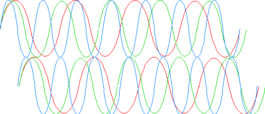

The amount that one ray is in front of the other, known as the path difference, is determined by two factors. The thickness of the crystal and the difference in the refractive indexes. Clearly with a thicker crystal the rays will become more separated than with a thinner one. As a result a tapered crystal will show a succession of bands of colour, and crystals which vary in thickness may show different colours depending on their thickness at that point. Equally a crystal in which there is a big difference between the refractive indexes of the two rays will have a bigger path difference than one of equal thickness that has rays in which the refractive indexes hardly differ. (Remember that the refractive index is inversely proportional to the speed of light in the material.) We thus have three related factors, the colour of the light, the difference between the refractive indexes (known as the birefringence), and the thickness of the material. If we know any two we can infer the third. If we know the thickness, as petrologists do because they grind their rock samples to a standard thickness, we can infer the birefringence with considerable accuracy by comparing the colour with that shown on the Michael Levy chart. Unfortunately when we look at pigment particles we cannot establish the thickness. However, we can get a general indication of whether the birefringence is high or low. Small particles are unlikely to be much thicker than their plan dimensions, but may of course be thinner, and this applies in particular to material that cleaves easily. Large fractured particles that show only low colours, grey or white are likely to have a low birefringence, a good example is quartz. Small or very small particles that show a good white, like titanium, must have a very high birefringence. Equally small particles that show some yellow or red must also have a very high birefringence, e.g. lead white or calcite.
The colours on normal anisotropic crystals start with black, grey, yellow, red, and this is known as the first order. The second order starts with blue, then green and continues with the next red. Third, fourth and fifth orders follow, each ending with a red and in each the colours become less intense. Eventually in the thickest parts, only a white is seen, this is known as a ‘high white’. The succession of colours is not a spectrum, but is known as the Newton scale of colours, it is often seen in thin films such as soap bubbles and in oil floating on water.
There are some materials in which the interference colours do not follow the order of the Newton scale. These colours are known as anomalous. Perhaps the most easily understood anomalous colours are those in which the colour of the crystal influences the interference colour. Iron reds for instance always appear a red, or reddish orange colour between crossed polars. Vermilion shows slightly more variation in the colours, but they are still confined to the red, orange and yellow part of the spectrum. Although, in most materials the refractive index of the blue light is slightly higher than that of red light, in some it is the other way round and with these materials we see blue where we would expect to see grey. Red lead and barium chromate are pigments where this type of anomalous colour is seen. With most pigments the direction of vibration of the two rays is the same for all colours, however, in a few, the directions in which the red rays vibrate is not the same as that of the green, and the directions of the green is not the same as that of the blue. Such materials are said to have a dispersed optic axis; and they have an undulose extinction and the interference colours are anomalous, the best example is distilled verdigris. We cannot establish the birefringece of a pigment which has an anomalous colour by looking at the colour between crossed polars. However, the colour, or colours, that we see may be characteristic of that pigment.
The red plate
Any anisotropic crystal will convert a ray of light vibrating in a single direction into two rays that vibrate at right angles to each other and which have different refractive indexes. When the two rays are resolved by the analyser into a single ray vibrating in one plane, the colour we see depends on the thickness of the particle and its birefringence (the difference between the refractive indexes of the two rays). This means that two crystals of the same thickness, but with different birefringences, will appear different colours when viewed between crossed polars. If we assume that both particles are in the 45° position; the colour will be higher on the Newton colour scale for the particle with the higher birefringence.
The red plate is a sheet of quartz, mica, gypsum or plastic that has a thickness such that the colour, when seen between crossed polars and oriented to the 45° position is a characteristic ‘red’ or puce colour. The plate is mounted in a slider so that it can be slid into, or out of, the optical path and is always in the 45° position. The position of the plate is fixed, and the direction in which the slow ray (higher refractive index) vibrates is marked on the slider with a line and the Greek letter gamma. Usually the slow direction is across the width of the slider, but the direction should be checked with a known substance, because some microscopes do not reverse the image top to bottom and in this case the effective direction of the red plate will be changed by 90°. The red plate has a variety of names and you may find it called a ‘first order red plate’, a ‘gypsum plate’, a ‘lambda plate’, a ‘wave plate’ or a ‘sensitive tint plate’.
If we view an elongated uniaxial particle between crossed polars without the red plate being inserted, the brightest colours, which will be the same (perhaps a grey), will occur when the particle points either NE/SW or NW/SE. If we insert the red plate we might find that the colour in the NE/SW direction is blue and the colour in the NW/SE direction is yellow. For the sake of this example, we will assume that the slow direction of the red plate is NE/SW, Although the red plate is always inserted above the particle, you may find it easier to understand if you think of the red plate as being inserted below the stage. It makes no difference to the result.
In this case the ray of light will pass through the red plate and be split into two rays vibrating NE/SW (the slow – high refractive index) and NW/SE (fast – lower refractive index). The rays will then pass on to the crystal which is rotated so that it is in one of the 45° positions. In other words the two rays from the red plate will line up with the fast and slow directions in the crystal. If the slow ray from the red plate passes directly into the slow lane of the crystal, the ray will become even more retarded compared with the other ray, (which will of course, have been in the fast lane of the red plate and continued in the fast lane through the crystal). The aggregate pathlength will be greater than either the pathlength of the particle or the plate, and the colour will move up the Newton scale from the first order red (of the red plate, which is what we see as a background) into the second order (perhaps a blue).
If we rotate the stage so that the crystal is now lying NW/SE the slow ray from the red plate will line up with the fast direction of the particle (equally the fast direction of the red plate will line up with the slow direction of the particle) and the aggregate pathlength will be less than the red plate, so the colour of the particle will move down the Newton scale and the particle will take on a first order colour (perhaps yellow).
Now we know that the slow direction of the red plate is NE/SW (because that was what was marked on the plate), and we know the direction in which the particle is lying when its slow direction lines up with that of the red plate (the colour moves up the Newton scale and becomes blue). So if the particle is elongated and it lies with its long axis NE/SW when the fast and slow directions of the particle correspond with those of the red plate, and can say that the particle has a slow length. This is sometimes referred to as positive elongation.
Particles with low polarisation colours, including most pigments, have colours with the red plate that are easily distinguishable e.g. blue – yellow. Obviously if the colour between crossed polars was a second order red then when the directions lined up it would go up to third order red, and when they were opposed it would appear with first order red. These reds can be distinguished but they are not as clear as the difference between blue and yellow. There are other compensators (the quartz wedge and the 1/4 wave plate) which provide more obvious differences when dealing with particles with higher polarisation colours. They work in essentially the same way, but are hardly ever needed with pigments.
The quartz wedge. If the slow direction of the wedge runs NE/SW, and one pushes the wedge IN SLOWLY in the direction of the crystal’s or fibre’s length, the coloured bands will move inwards if the length is slow (i.e. positive sign of elongation). The bands will move out if the sign is negative. The effect will be reversed if the wedge’s slow direction is NW/SE or the particle or fibre is arranged NW/SE.
Uniaxial crystals and twinkling
The effect that a uniaxial crystal will have on plane polarised light will depend on the orientation of the crystal. In most positions the ray will be converted into two rays. One of these will vibrate in the plane formed by the optic axis and the direction of propagation, and the other will vibrate at right angles to it. However, there are three positions in which only a singe ray will emerge and it will vibrate in the same plane as the incident ray. N.B. The optic axis is not something that runs down the centre of the crystal like the axle of a wheel, it is a direction in the crystal. This means that any fragment from that crystal includes the optic axis.
1. When the crystal is lying so that the optic axis is normal to the stage of the microscope, the refractive index which will be observed with this ray will be w (omega) and it will be unaffected if the stage is turned. Consequently in this position the crystal will behave as if it were isotropic.
2. When the crystal is lying so that its optic axis is parallel to the plane formed by the direction in which the incident ray is travelling and its vibration direction; the refractive index will be e (epsilon) if the optic axis is also parallel to the stage, and e’ (epsilon prime) if it is not.
3. When the stage is turned through a right angle from position 2 above, the w refractive index will be seen irrespective of whether the optic axis is parallel to the stage or not.
It will be seen from the above that a uniaxial crystal (unless the optic axis is normal to the stage, in which case one will see the w index all the time), must exhibit the w refractive index twice in each complete rotation of the stage. Where w corresponds to the refractive index of the mounting medium, each of the crystals of that substance will ‘disappear’ twice when the stage is rotated completely. This phenomenon is known as ‘twinkling’.
It should be noted that e may be higher than w – in which case the material is known as uniaxial positive – or lower when it is known as uniaxial negative.
Calcite is a uniaxial negative material with w = 1.658 and e = 1.46. However, in view of calcite’s excellent cleavage, few particles will lie with the optic axis parallel to the stage, and most will exhibit an e’ of 1.566. Because w for calcite is similar to the refractive index of Meltmount 1.662, any calcite crystals will twinkle when the preparation is viewed in plane polarised light and the stage of the microscope rotated.
Refractive index relative to the mounting medium
There are three methods of establishing whether the refractive index of a particle is higher or lower than the medium in which it is immersed. You can use the Becke line, the central illumination technique or the modified Van der Kolk method. Each has advantages and disadvantages, and all should be practiced. It is wise if there is any doubt about the result to check it against one of the others.
The Becke line
Focus the particle carefully, then close the aperture diaphragm down a little – until the edges of the particle harden a little. Then watch the particle and move the fine focus backwards and forwards very slightly. You should see a light line move towards the centre of the particle or towards its edge. This line is the Becke line. You will find that if you increase the distance between the objective and the slide the line will move towards the medium with the greater refractive index. Thus if the particle is mounted in Meltmount with a refractive index of 1.662 and the particle is smalt with a refractive index of about 1.5, the Becke line will move towards the edge of the particle and the medium when the distance between the objective and the slide is increased. If the same particle had been mounted in water (refractive index of 1.0) the Becke line would have moved away from the water and the edge towards the centre of the particle. The Becke line works well with broken particles that are rather large by pigment standards. It is only possible to check whether particles have a refractive index that is higher or lower than the medium, one at a time. N.B. it is important that the line you observe is within the confines of the particle. Bright lines moving away from the particle in the medium can be caused by refraction, and occur with particles that have a greater or lower refractive index when compared to the medium. The other point to remember is that some particles with unusual shapes, may create Becke lines that go the ‘wrong’ way. It is therefore important to check several particles.
The central illumination technique
This technique is really a modification of the Becke line method and was, we think, given its name by Walter McCrone. It can be used on particles with rough surfaces and small particles, but takes some practice before one is likely to get consistent results if the particles are very small. One should close the aperture diaphragm down slightly. Then, if one focuses a particle and increases the distance between the objective and the slide you should see that the particle will brighten slightly towards the centre if the refractive index of the particle is greater than the medium. If the refractive index is lower, the particle will become dull as the bright area expands and then leaves the edge of the particle. This technique can be applied to particles where it is difficult to observe a Becke line. If the particle is very small and has a refractive index that is greater than the medium, a tiny hard bright point of light will form on the top of or just above the particle. Again the technique must be applied to each particle that one wishes to check.
The modified Van der Kolk method
The original Van der Kolk method involved the use of a special substage condenser, that was left wide open, and included an insert which blocked out half the lens. One also needed an objective in which the opposite half was blocked. Walter McCrone found that it is possible to work by merely blocking off half the substage condenser by holding a piece of card close to the bottom of the mount. However, our experience is that on a number of microscopes this reverses the effect. The effect is also reversed if the substage condenser is not focused perfectly. On the whole the results seemed unreliable. The simplest and most reliable version that we have found was suggested to us by Stefan Wülfert and involves partially inserting the analyser so that a darkened area forms on one side of the field of view, and covers perhaps a quarter of it. If one looks at particles that are near to this darkened area one will see that one side of each particle is slightly shadowed and the other side is bright. If the shadow beside the particle is nearer to the darkened area the particle has a refractive index that is higher than the medium, and if the shadow is on the side away from the darkened area the particle has a lower refractive index. The authors have not found any microscopes where this does not work, but it would be wise to check some particles with known refractive indexes, before using the technique to establish the relative refractive index of an unknown material. One of the advantages of this technique is that a number of particles can be checked at the same time, another is that the aperture diaphragm should be left where it normally is, and therefore does not need to be opened once the test has been made. You might find that partially inserting the red plate instead of the analyser could be more convenient on some microscopes.
When using the modified Van der Kolk method some people find that the problem is remembering which side of the particles the shadow should be for a higher or lower refractive index. If you find this a difficulty the following might help:
CIA = Close Is Above. The shadow on the particle is close to the large shadow in the field of view
or SEL = Separate Equals Lower. The shadow on the particle is separated from the large shadow by a bright edge on the other side of the particle.
English currency pre 1971
The currency in England was decimalized in 1971, but before that it had remained much the same for several centuries. The pound was divided into 20 shillings and each shilling could be divided into 12 pence or pennies, thus there were 240 pennies in a pound. Pennies could be divided into four farthings or two half pence – usually pronounced “ha’pennies” with the “a” pronounced like the “a” in “may”. The sign for the pound was the same that is used today. Shillings were indicated by an “s” and pence, by the letter “d”, which stood for denarius, a small Roman silver coin. Halfpence and farthings were represented by the relevant fraction. In accounts or lists of prices the amounts are usually in three columns often headed with the letters £, s, d. Where a single price occurs it is usually written on a single line e.g. £4 19s 11¾ represented four pounds, nineteen shillings and eleven pence three farthings; this was only one farthing short of five pounds. Where there were no pounds in a written price, the “d” and “s” were usually omitted and the the shillings and pence were divided by a solidus or slash, e.g. 2/6 for two shillings and six pence; 4/11½ for four shillings and eleven pence and a halfpenny. Where there were no pence the missing figure was replaced by a dash, not a 0: e.g.. 5/- for five shillings. When only pence were required the amount was followed by a “d” e.g. 10d for ten pence.
In addition to the pound there was the guinea which was worth one pound and one shilling, so that 25 guineas was the equivalent of £26 5s 0d. The professional classes, such as solicitors, barristers, architects and artists usually charged in guineas, while tradespeople, such as carpenters and house painters would charge in pounds.
Self study section
Questions
You need to make up, or get access to, as many slides of pigments as possible. A recommended list of pigments is given in the lists below. When you have the slides you can pick a pigment from one of the lists below and try to answer questions about what you see. The two lists are the same, but if you pick a pigment in the novice list, you will find that the questions have been made easier, and more help is given, than if you pick from the advanced list.
Novice
Azurite
Put a slide of azurite on the stage, and view it at a magnification of about x500. Move the slide so that you see more than one field of view but do not rotate the stage yet. Look at the shapes of the particles, What do they tell you about how the pigment was made. Try to find out whether the refractive index of the particles is higher or lower than the mountant; use both the Becke line, and modified Van der Kolk methods. Turn up the light and check what effect the Chelsea filter has. Write down what you can see.
What do you see?
Lead white
Put a slide of lead white on the stage, and view it at a magnification of about x500. Move the slide so that you see more than one field of view but do not rotate the stage yet. Look at the shapes of the particles, What do they tell you about how the pigment was made. Try to find out whether the refractive index of the particles is higher or lower than the mountant; use both the Central illumination, and modified Van der Kolk methods. Write down what you can see.
Chalk
View a slide of chalk that has been mounted in meltmount n=1.662, in plane polarised light. Rotate the stage, but do not cross polars.
Describe the colour of the particles. Do you see any particles with specific shapes? Consider the relief. Do all the particles appear to have the same refractive index? Use both the Central illumination, and modified Van der Kolk methods to determine whether the refractive index of the particles is greater or less than that of the mountant.
Advanced
Azurite
Put a slide of azurite on the stage and write down all the features that you can see. Observe the slide in plane polarised light, rotate the stage, and then cross polars. Use any accessories such as the Chelsea filter that you feel might help. Do not forget to move the slide so that you see a wide range of particles. When you have made your notes.
Lead white
Look at a slide of lead white, in plane polarised light, between crossed polars and between slightly uncrossed polars. Do not forget to move the slide so that you see a wide range of particles. Describe what you see, and explain what the observations imply.
Answers
Mactaggart, P. & Mactaggart, A. (June 2007) ‘Menu of techniques’ In: Pigment ID using Polarised Light Microscopy from: https://academicprojects.co.uk/menu-of-techniques/
