
Refractive index 2
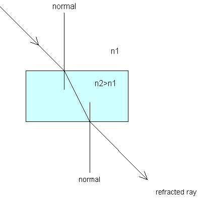
Notice the way in which the light ray bends towards the normal when passing from a medium with lower refractive index to one with a higher refractive index; and away from the normal when entering a medium with a lower refractive index.
Illumination systems
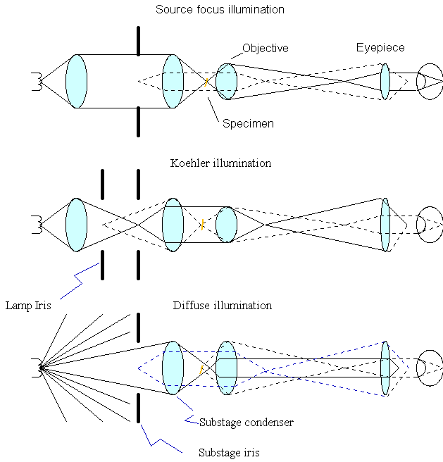
There are four main ways in which a specimen can be illuminated: Source focus, Köhler, Diffuse and Daylight.
Source focus
This is sometimes referred to as “critical illumination” or “Nelsonian illumination” after Edward Nelson (1851-1938). This is seldom used today in its purest form. Essentially the light source, whether a cloud, a lamp flame or a featureless lamp is imaged onto the specimen. The lamp which was used was called a pointa lamp and these have not been available for many years. Modern filament lamps cannot be used directly as an image of the filament would be visible on the specimen. Today a piece of ground glass may be put in front of the lamp and the ground surface taken as the illuminating source. Sometimes this is combined with the lenses of the lamp by roughening a surface of one of the lenses. The lamp condenser, or “collector” is designed so it they produces a parallel beam of light which is focused on the slide by the substage condenser. There is no field diaphragm as it would duplicate the aperture diaphragm and would not control the area that is illuminated. This system can give excellent results when used with a well corrected lamp and substage condenser. As the ground glass can reduce the amount of light that reaches the specimen by as much as 70% it may not be suitable for work where high levels of light are required. Where a microscope has been designed for use with source focus or daylight the substage condenser may not be able to illuminate the full area of the slide with a low power objective and may display more spherical aberration, when the microscope is set up for use with Köhler illumination, than it would if used with source focus, In addition the field diaphragm may act like a second aperture diaphragm and restrict the amount of light. This means that that opening the aperture diaphragm may not enable a high NA objective to be filled to 70% unless the field diaphragm is opened further than is should be. Unfortunately, opening the field diaphragm in these circumstances, while improving the resolution, will also have the effect of reducing contrast. It is possible to tell if the substage condenser has been designed to accept a parallel beam of light, by focusing a slide with a low power objective, and adjusting the focus of the substage condenser to see whether it will readily bring the image of distant trees or a cloud in the plane of the specimen. When doing this, it is important not to make any of the adjustments on the condenser, such as removing the top lens, that one would normally do for low power work. If the microscope has no mirror because it has a built in lighting system, use a small hand mirror. When you have finished adjusting the lamp and substage condenser, adjust the aperture diaphragm so that it is 70-80% open. Either use a Bertrand lens, or take an eyepiece out so that you can see what you are doing.
Köhler illumination
This system was devised by August Köhler (1866-1948) Unlike Nelson who was concerned to obtain the best resolution from the lens in the center of the field of view, Köhler was interested in photomicrography and wanted to achieve an evenly, and strongly illuminated field of view even if the lamp varied in intensity over its surface. Correctly set up, Köhler illumination focuses the light in the plane of the field diaphragm onto the specimen. Where no ground glass is incorporated into the lamp condenser or between it and the lamp, the system provides plenty of light. Today there is a tendency to place a piece of ground or etched glass immediately in front of the bulb in the lamp and this reduces the available intensity of light considerably. The advantage to the manufacturer is that he does not have to provide for the centring of the bulb or the focusing of the lamp which he would have to do if the direct light source was the filament. The substage condenser, if it is a highly corrected one, should be designed to focus rays coming from a short distance away rather than from infinity as in the case of Nelsonian illumination. Using a substage condenser designed for source focus in a Köhler system can introduce spherical aberration.
Diffuse illumination
This uses a pearl light bulb close to the mirror. Focus a slide and adjust the mirror to give you the maximum amount of light, then focus the substage condenser so that you can see the surface of the bulb. Finally just defocus the substage condenser so that the grain of the bulb is no longer visible. If you have too much light move the lamp further from the mirror and start again. If you cannot see the surface of the bulb, hold the tip of a pencil against the bulb and focus on that. When you have finished adjusting the lamp and substage condenser, adjust the aperture diaphragm so that it is 70-80% open. Either use a Bertrand lens, or take an eyepiece out so that you can see what you are doing.
Daylight
In a sense this is similar to source focus illumination as the rays of light are parallel. Focus a slide, and focus with the substage condenser on a distant white cloud. NEVER attempt to focus on the sun! The only problem with this technique is unreliability of British weather, and the fact that one cannot work after sundown. However in some parts of the world this is less of a problem.
Dispersion Staining
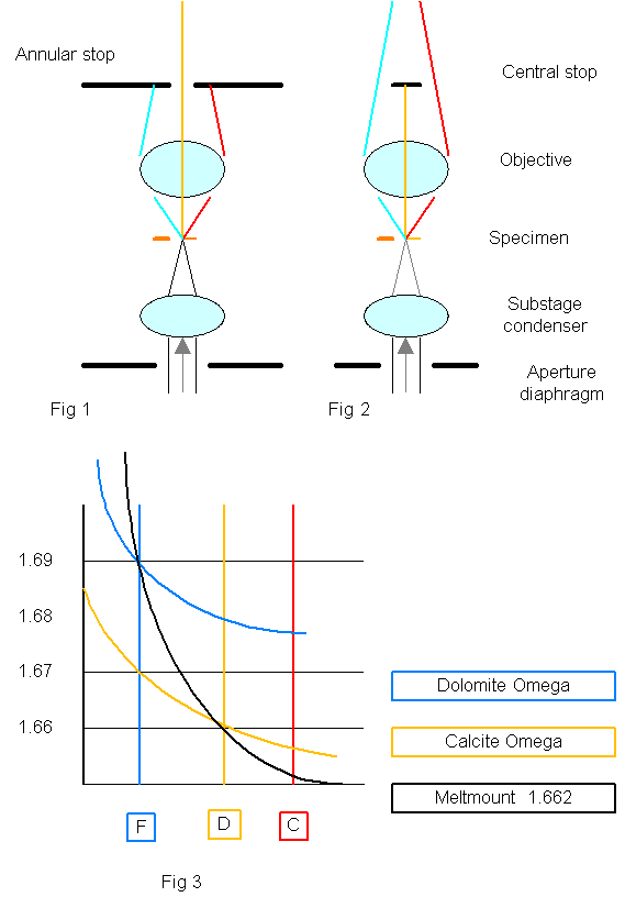
Dispersion staining is a technique which is based on the fact that the refractive index for a particular material varies according to the wavelength of the light. The refractive index is usually quoted for the wavelength of the sodium light, or D line, about 589 nanometers. The F line is centered on the blue of the spectrum and is about 486 nm and the C line is similarly centered on the red at about 653 nm. In most materials the refractive index will be higher for shorter wavelengths and lower for longer ones.
In the graph, Fig 3 above, the refractive index has been plotted against wavelength for Meltmount, and the omega rays of calcite and dolomite. It will be seen that the omega ray of calcite has the same refractive index as meltmount for a wavelength that roughly corresponds with the D line; whereas the omega ray of dolomite roughly corresponds with that of meltmount at the F line.
A special objective is required for dispersion staining. The objective, which provides only a low magnification (usually about X 10) is fitted with either a diaphragm or a solid ring above the lens, alternatively it has a central stop fitted at the same level. In use, the aperture diaphragm is closed until it appears about the same size as the ring or diaphragm of the objective. If a commercial dispersion staining objective is not available it is possible to paint a suitable stop in opaque black paint on a small circular cover slip, and to fit it to the back of a x 10 objective. It will be found that a high level of light is required, particularly with the central stop. Because only the central part of the objective is used to form the image when the annular stop is used the resolution will be low and the colour at the edges of small particles may not be able to be seen clearly. Using a central stop improves the resolution, and the particles are seen against a dark background, but the effect can be confusing if there is any dirt on the slide or very fine particles are present in the preparation, as a result, the annular stop is easier to use until considerable experience has been acquired. See the Particle Atlas for more information and for graphs showing the refractive index plotted against wavelength for a wide range of materials.
Some samples of calcite and dolomite can be distinguished with a dispersion staining objective when they are mounted in Meltmount. To see the effects put a preparation of rather large calcite particles, on the stage and rotate it. It will be found that when the particles are arranged with the slow, omega, direction corresponding to that of the analyzer, the yellow rays from the edges of the particles will not deviate and will be able to pass through the small hole at the back of the objective. The red and blue rays will be refracted and will be stopped by the flanges of the stop (see Fig 1). The edges of the particles will therefore appear yellow as most of the spectrum, apart from yellow has been removed. If the central stop is used, the yellow rays will be stopped and the blue and red rays will pass through so that the edges will appear bluish. If the same experiment is tried with dolomite it will be found that with the annular stop the edges will appear blue as the yellow and red rays are refracted and stopped by the dispersion stop, and with the central stop the blue rays will be stopped and the edges of the particles will appear yellowish.
Dolomite and calcite are the only pigments that are likely to show dispersion staining colours in Meltmount. By using refractive index fluids the range of materials can be extended. Barytes (BaSO4) and celestine (SrSO4) can be differentiated in Cargille fluid n= 1.62 where barytes will appear bluish with an aperture stop and brownish with a central one: celestine appears yellow with green edges with an aperture stop and blue and magenta with a central one. As the extent of the dispersion varies from one material to another further indications of identity can be gained by checking the colour in fluids of slightly different refractive index.
Mactaggart, P. & Mactaggart, A. (June 2007) ‘Optics’ In: Pigment ID using Polarised Light Microscopy from: https://academicprojects.co.uk/optics/
